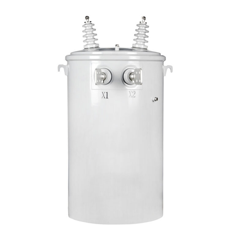
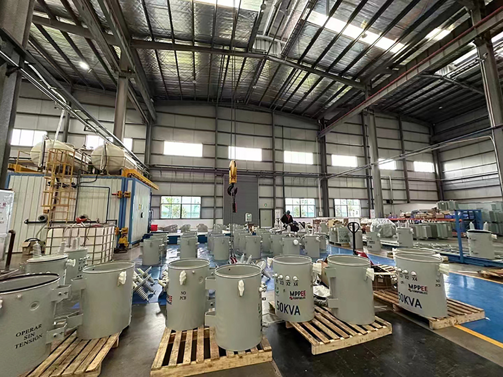
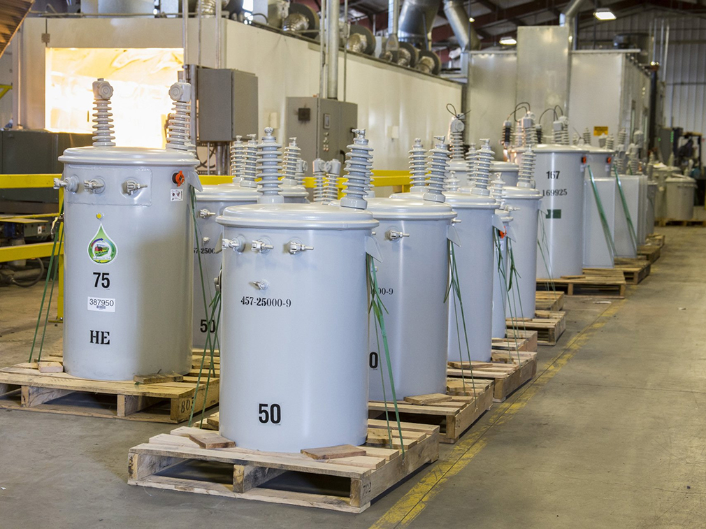
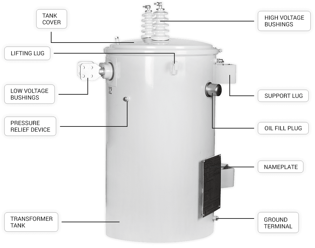
Dry Transformer and Oil Immersed Transformer Manufacturer

High and Low Voltage Switchgear GGD

low voltage switchgear GGD

High and Low Voltage Switchgear

low voltage switchgear GGD

Low Voltage Switchgear GGD

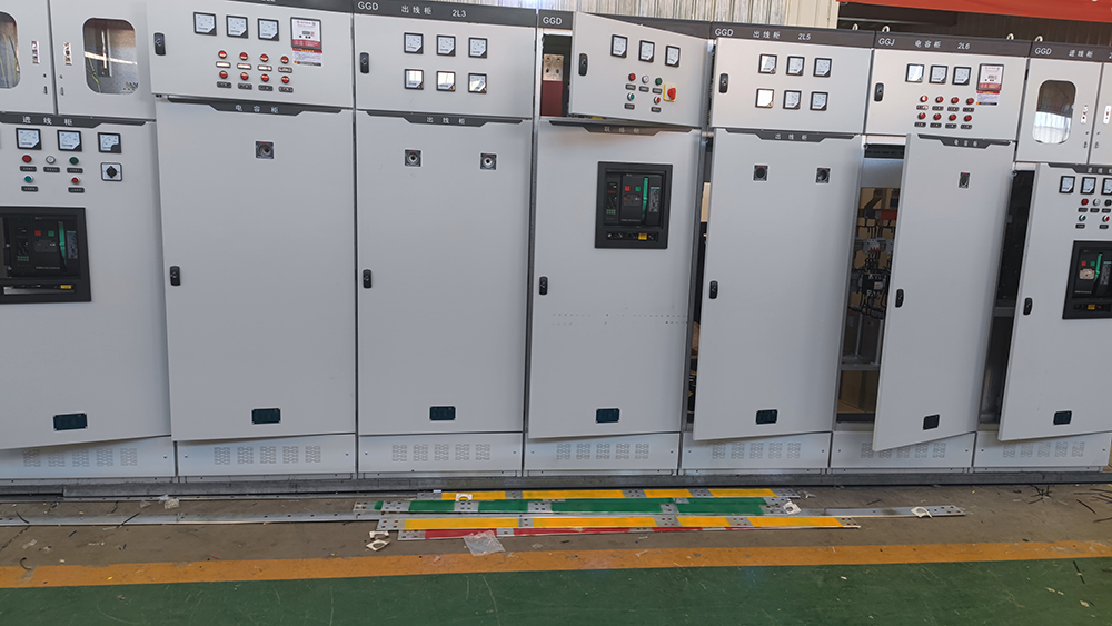
The GGD low voltage switchgear is suitable for power users such as power plants, substations, and industrial enterprises. It is used in AC power distribution systems with a frequency of 50Hz (60Hz), a rated working voltage of 380V (400V) or 660V, and a rated current of up to 3150A for the conversion, distribution, and control of electrical energy for power and lighting equipment. This product features high breaking capacity, good dynamic and thermal stability, and a rated short-time withstand current of up to 50kA. It offers flexible electrical schemes, convenient combinations, strong practicality, innovative structure, and high protection levels.

Introduction of Low Voltage Switchgear GGD

Some structural features of Low Voltage Switchgear GGD:

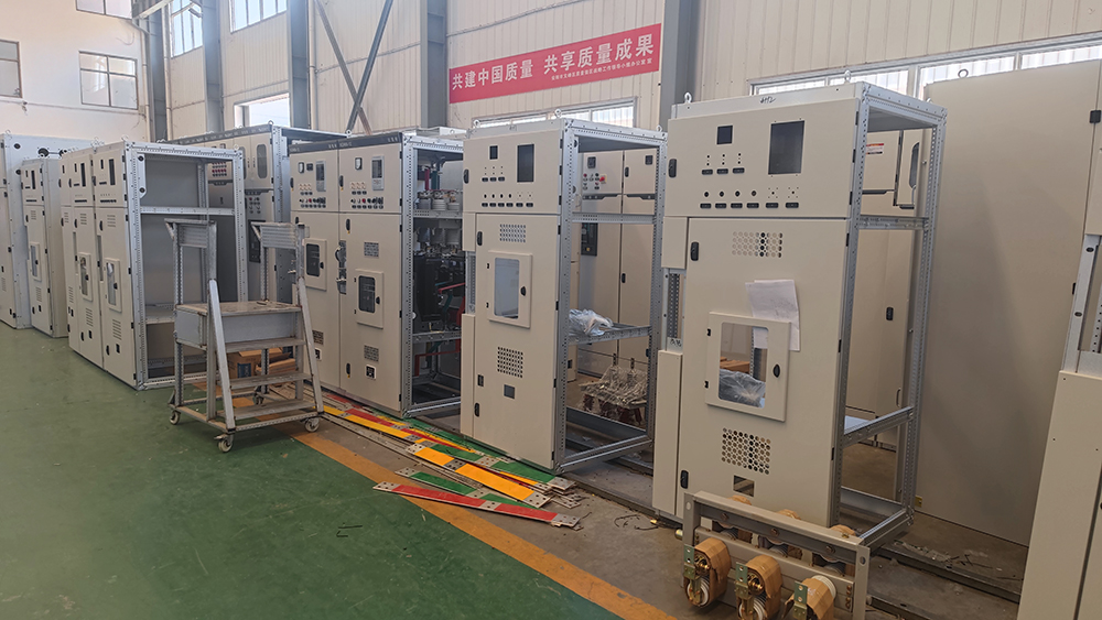
  1. The cabinet body of the GGD distribution cabinet adopts a universal cabinet design, with the frame constructed from 8MF cold-formed steel that is partially welded and assembled. The frame components and specialized supporting parts are produced and supplied by our company to ensure the precision and quality of the cabinet body.
  2. The design of the low voltage switchgear GGD fully takes into account the heat dissipation issues during operation. There are varying numbers of ventilation slots at both the upper and lower ends of the cabinet. When the electrical components inside the cabinet generate heat, the warm air rises and is expelled through the upper ventilation slots, while cool air continuously enters the cabinet through the lower slots. This creates a natural ventilation pathway from the bottom to the top of the sealed cabinet, effectively achieving heat dissipation.
  3. The cabinet doors are connected to the frame using pivot-type hinges, allowing for easy installation and removal.
  4. The surface of the cabinet body is treated using a high-pressure electrostatic powder coating process. This method enhances the durability and aesthetic appeal of the cabinet, providing a smooth and attractive finish while ensuring strong adhesion and resistance to wear and corrosion.

Technical Specification of Low Voltage Switchgear GGD

modelRated Voltage (V)Rated Current(A)Rated Short Circuit Breaking Current (kA)Rated Short Circuit Withstand Current (1s)(kA)Rated Peak Withstand Current (kA)
GGD1380(400)(660)A1000151530
B600(630)
C400
GGD2380(400)(660)A1600(1500)303063
B1000
C1250
D600(630)
GGD3380(400)(660)A31505050105
B2500
C2000
D1600(1500)
E1250
F1000

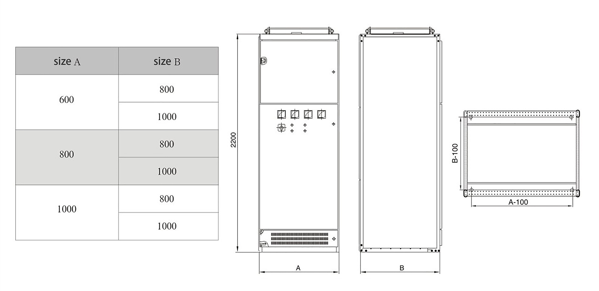
Drawing of Low Voltage Switchgear GGD

low voltage switchgear GGD structure
Please enable JavaScript in your browser to complete this form.

Get in Touch

High and Low Voltage Switchgear GCK

high and low voltage switchgear GCK

High and Low Voltage Switchgear

high and low voltage switchgear GCK

Low Voltage Switchgear GCK

The GCK low-voltage switchgear is suitable for use in power plants, metallurgical rolling, petrochemical industries, light industry and textiles, electric power, machinery, docks, hotels, and other locations. It is designed for three-phase four-wire or three-phase five-wire systems, with a rated operating voltage of 380V (400V) or 660V, a rated current of up to 4000A, and a rated frequency of 50Hz (60Hz) for power distribution and motor control in electrical systems.

Introduction of Low Voltage Switchgear GCK

Some structural features of Low Voltage Switchgear GCK:

  • GCK’s basic cabinet frame is designed as a modular assembly structure. The frame is made of hot-rolled steel (STHC), and the FA profiles are positioned using angle plates and connected with bolts, resulting in a non-welded structure. The forming dimensions, hole sizes, and equipment clearances of the components are standardized to modular dimensions.
  • The internal structural components are treated with galvanization.
  • The external structural components are treated with acid pickling and phosphating, followed by high-pressure electrostatic spraying.
  • The structural components have strong versatility and high mechanical strength.
  • The upper part of the cabinet is the main busbar chamber, the front part is the electrical chamber, and the rear part is the cable entry and exit chamber. Steel plates or insulating boards are used for isolation between the chambers to ensure safe operation.

Technical Specification of Low Voltage Switchgear GCK

Main Circuit Rated Voltage (V)AC380(400)、(660)
Auxiliary Circuit Rated Voltage (V)AC110、220(230)、380(400) DCII0、22
Rated Frequency (Hz)50(60)
Rated Insulation Voltage (V)AC600(1000)
Rated Current(A)Horizontal Connection1000、1250、1600、2000、2500、3150、4000
Vertical Busbar (MCC)630;800
Bus Rated Short Time Withstand Current (kA/1s)30;50;80
Bus Rated Peak Withstand Current (kA/0.1s)63;105;176
Power Frequency Test Voltage (V/min)Main Circuit2500
Auxiliary Circuit1800
Hand Shank3750
IP CodeIP30、IP40

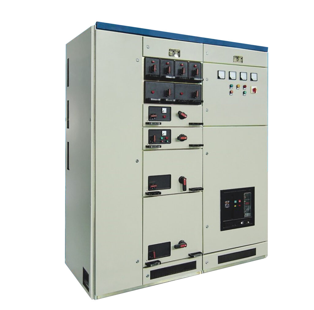
Drawing of Low Voltage Switchgear GCK

low voltage switchgear GCK structure
Please enable JavaScript in your browser to complete this form.

Get in Touch

High and Low Voltage Switchgear GCS

high and low voltage switchgear GCS

High and Low Voltage Switchgear

high and low voltage switchgear GCS

Low Voltage Switchgear GCS

The GCS low-voltage switchgear is a withdrawable switchgear that possesses high technical performance indicators, adapts to the development needs of the power market, and it is very competitive.

Introduction of Low Voltage Switchgear GCS

The low voltage switchgear GCS is suitable for distribution systems in industries such as power plants, petroleum, chemical, metallurgy, textiles, and high-rise buildings. In places with high levels of automation, such as large power plants and petrochemical systems, where interfaces with computers are required, it serves as a low-voltage complete distribution device for power generation and supply systems. It operates at a three-phase alternating current frequency of 50 (60) Hz, with a rated working voltage of 380V (400V) or 660V, and a rated current of 4000A and below, used for distribution, centralized motor control, and reactive power compensation.

  • The main frame assembly design is available in two forms: a fully assembled structure and a partially welded structure (side cabinets and cross beams), allowing users to choose according to their needs.
  • The various functional compartments of the assembly are isolated from each other. These compartments are divided into functional unit rooms, busbar rooms, and cable rooms, with each room serving an independent function.
  • The horizontal main busbars are arranged in a flat configuration at the rear of the cabinet to enhance the busbar’s ability to withstand electrodynamic forces. This is a fundamental measure to ensure that the main circuit of the device has a high short-circuit breaking capacity.

Technical Specification of Low Voltage Switchgear GCS

Main Circuit Rated Voltage (V)AC380(400)、(660)
Auxiliary Circuit Rated Voltage (V)AC110、220(230)、380(400) DCII0、22
Rated Frequency (Hz)50(60)
Rated Insulation Voltage (V)AC600(1000)
Rated Current(A)Horizontal Connection1000、1250、1600、2000、2500、3150、4000
Vertical Busbar (MCC)630;800
Bus Rated Short Time Withstand Current (kA/1s)30;50;80
Bus Rated Peak Withstand Current (kA/0.1s)63;105;176
Power Frequency Test Voltage (V/min)Main Circuit2500
Auxiliary Circuit1800
Hand Shank3750
IP CodeIP30、IP40

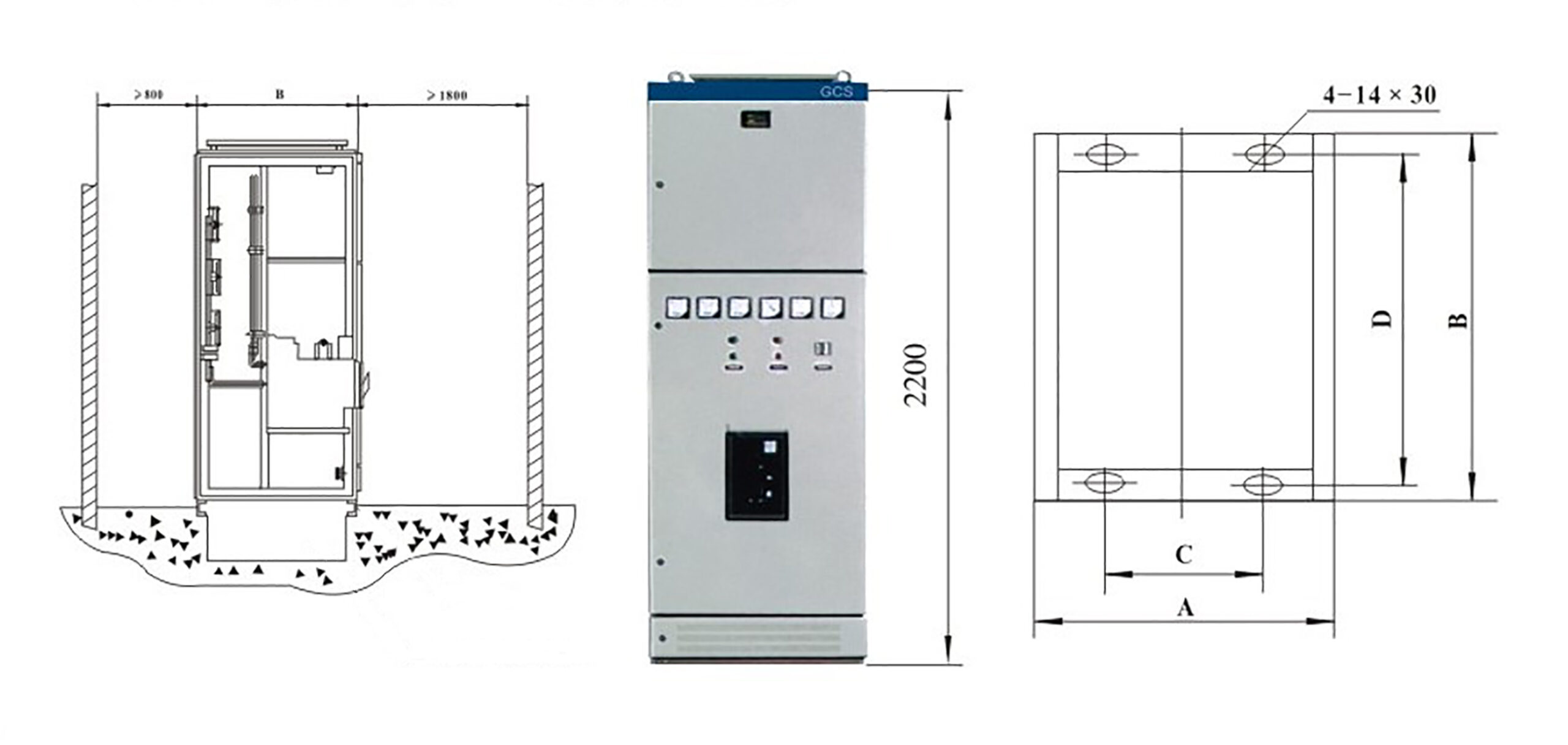
Drawing of Low Voltage Switchgear GCS

Please enable JavaScript in your browser to complete this form.

Get in Touch

High and Low Voltage Switchgear MNS

low voltage switchgear MNS

High and Low Voltage Switchgear

low voltage switchgear

Low Voltage Switchgear MNS

The MNS low-voltage switchgear features a flexible, modular, multifunctional design with reliable and safe performance. It is suitable for use in various fields such as metallurgy, petroleum, chemical industry, mining enterprises, and infrastructure. The switchgear is designed for three-phase AC systems with a frequency of 50 (60) Hz, a rated operating voltage of 380V (400V) or 660V, and a rated current of up to 4000A, serving in power generation and supply systems, as well as in all low-voltage systems including distribution and centralized motor control.

Introduction of Low Voltage Switchgear MNS

The low voltage switchgear MNS design fully takes into account the requirements of a wide range of power users and design departments, meeting the evolving needs of the power industry for increased capacity centralized control, convenient installation and maintenance, and reduced accident response time, while ensuring safety, economy, rationality, and reliability. The product features strong switching capability, high breaking capacity, good dynamic stability, flexible electrical schemes, convenient combination, strong series compatibility and practicality, as well as an innovative structure. Additionally, it can be combined and used in conjunction with withdrawable switchgear.

Technical Specification of Low Voltage Switchgear MNS

Main Circuit Rated Voltage (V)AC380(400)、(660)
Auxiliary Circuit Rated Voltage (V)AC 110、220(230)、380(400) DCII0、220
Rated Frequency (Hz)50(60)
Rated Insulation Voltage (V)AC660、(1000)
Rated Current(A)Horizontal Connection1000、1250、1600、2000、2500、3150、4000
Vertical Busbar (MCC)630;800
Rated Short Time Withstand Current (kA/1s)Horizontal Busbar30;50;80
Vertical Busbar30;50;80
Rated Peak Withstand Current (kA/0.1s)Horizontal Busbar63;105;176
Vertical Busbar63;105;176
Power Frequency Test Voltage (V/min)Main Circuit2500
Auxiliary Circuit1800
Hand Shank3750
IP CodeIP30、IP40

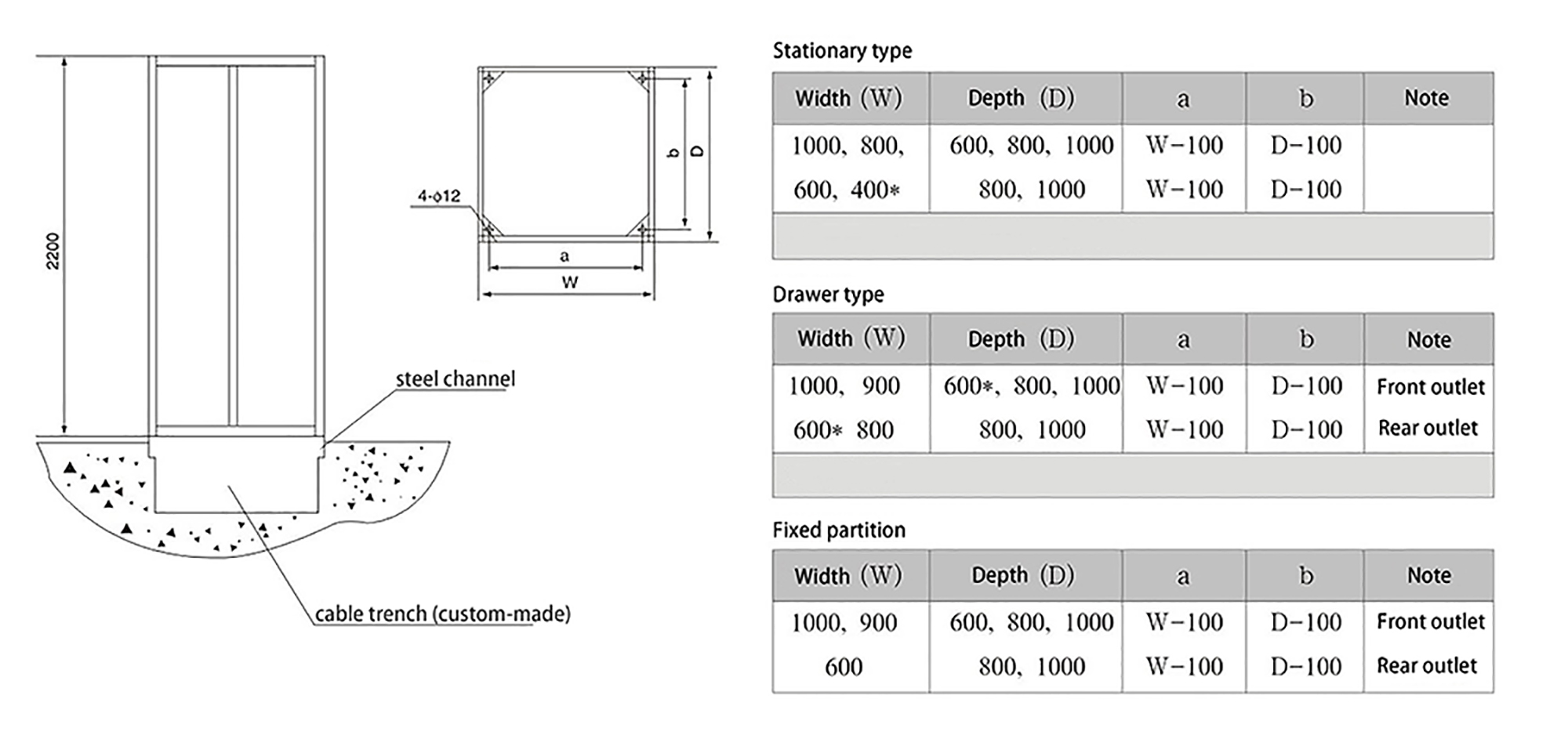
Drawing of Low Voltage Switchgear MNS

low voltage switchgear structure
Please enable JavaScript in your browser to complete this form.

Get in Touch

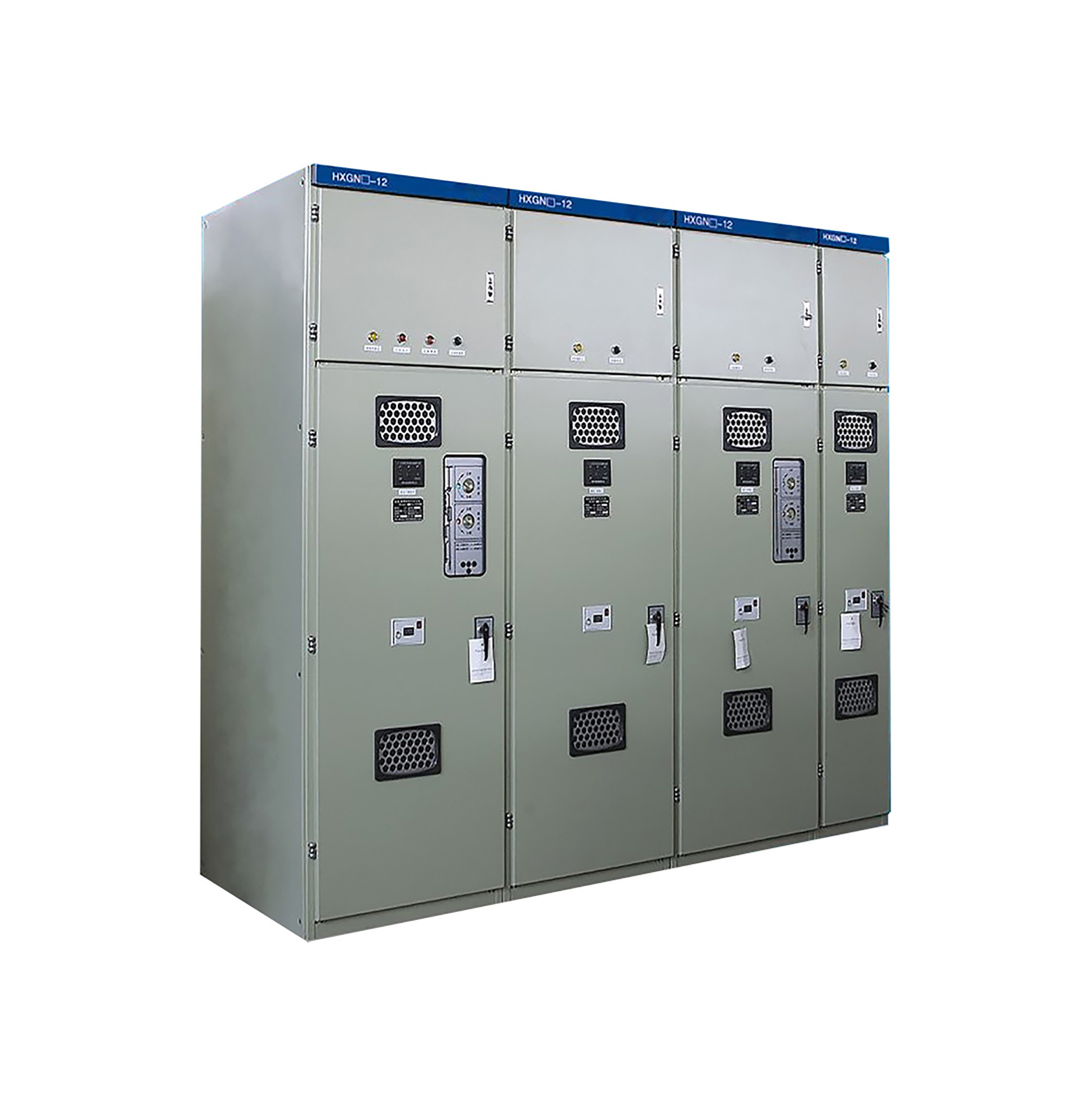
High and Low Voltage Switchgear HXGN-12

high and low voltage switchgear HXGN-12

High and Low Voltage Switchgear

high and low voltage switchgear XGN2-12

High and Low Voltage Switchgear HXGN-12

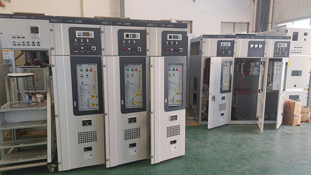
The HXGN-12 switchgear is suitable for distribution systems in industrial and mining enterprises, residential communities, high-rise buildings, and school parks. It serves as an indoor three-phase AC power supply unit and terminal distribution equipment for 12kV, 50Hz ring network applications. It can switch on or off the rated load current and the no-load current of transformers, as well as disconnect or connect overhead lines, cable lines, or capacitive currents over a certain distance. The load switch-fuse combination cabinet can interrupt the rated short-circuit current in a single operation.

Introduction of High and Low Voltage Switchgear HXGN-12

Some structural features of High and Low Voltage Switchgear HXGN-12:

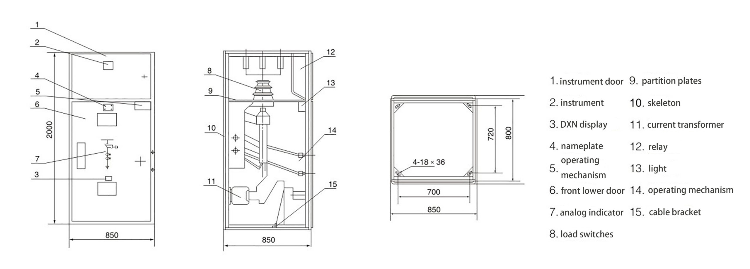
The HXGN-12 High and Low Voltage Switchgear is constructed from 8MF type steel, which is partially welded and then bolted together. It primarily houses the FZN21-12 type two-position vacuum load switch, which is used in conjunction with a fuse equipped with an impactor to form a combined electrical device. This type of switchgear can be flexibly equipped with current transformers (CT), potential transformers (PT), and ZnO surge arresters. Its base is fitted with a removable access cover for easy cable entry, and for overhead cable entry, a busbar channel can be added according to user requirements.

Technical Specification of High and Low Voltage Switchgear HXGN-12

No.ItemUnitData
1Rated VoltageKV7.2/12
2Main Busbar Rated CurrentA400;630;1250
3Rated CurrentIncoming CabinetA400;630;1250
Outlet CabinetA125
4Rated Short time Withstand CurrentKA20
5Rated Peak Withstand CurrentKA31.5
6Rated Short Circuit Closing Current Peak ValueKA50
7Rated Active Load Breaking CurrentA630
8Rated Closed Loop Breaking CurrentA630
9Rated Cable Charging CurrentA10
10Ground Switch Rated Short Time Withstand CurrentKA20
11Ground Switch Rated Peak Withstand CurrentKA50
12Ground Switch Rated Short Circuit Closing Current Peak valueKA50
13Rated AC Current of Combination ApparatusA3150
141min Power Frequency Withstand VoltageInterphase Relative Vacuum FractureKV42
Isolating Distance48
15Lightning Impulse Withstand VoltageInterphase Relative Vacuum FractureKV75
Isolating Distance85
16Mechanical LifeVacuum Load Switchtime10000
Isolation Knife Grounding Knife2000
17Load SwitchAverage Closing Speedm/S0.6±0.2
Average Opening Speedm/S1.1±0.2
Three-phase Different PhasesmS≤2
18Fuse for Combined AppliancesMaximum Rated CurrentA125
Rated Short Circuit Breaking CurrentKA31.5
19IP CodeIP2X

Drawing of High and Low Voltage Switchgear HXGN-12

HXGN-12 structure
Please enable JavaScript in your browser to complete this form.

Get in Touch

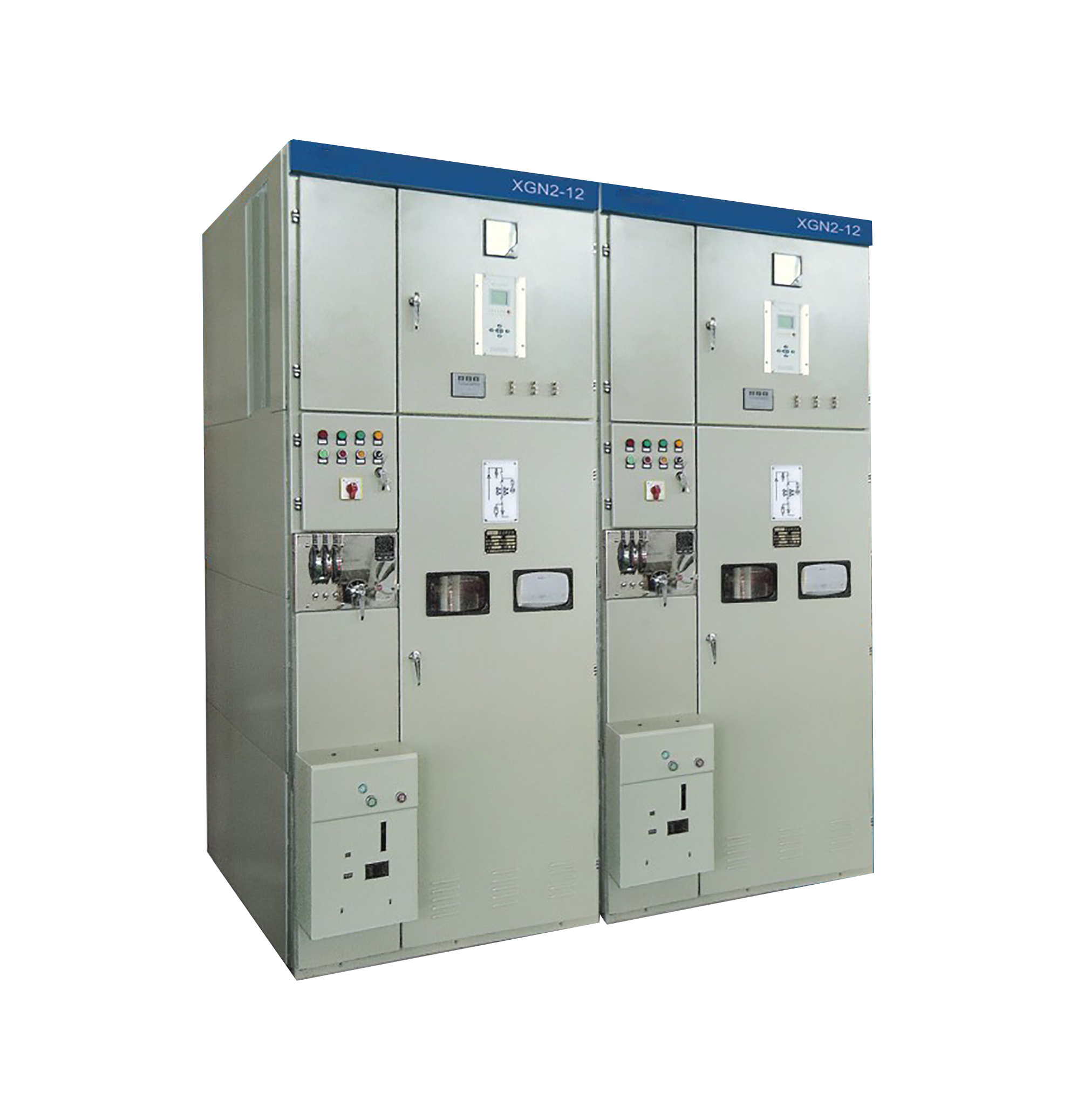
High and Low Voltage Switchgear XGN2-12

high and low voltage switchgear XGN2-12

High and Low Voltage Switchgear

high and low voltage switchgear

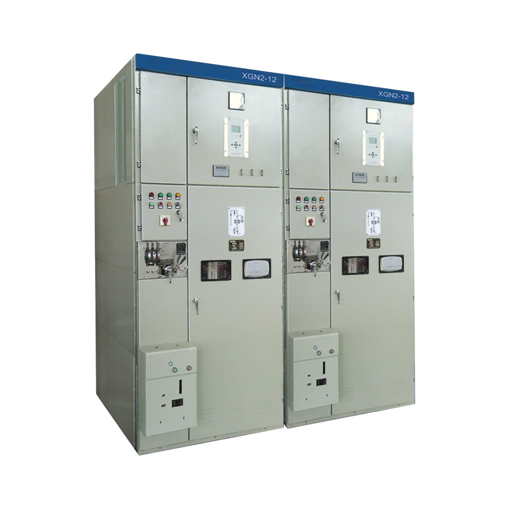
High and Low Voltage Switchgear XGN2-12

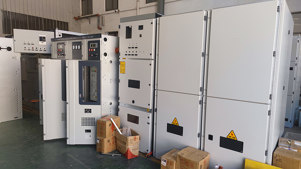
The XGN2-12 switchgear features a metal-enclosed box structure. The cabinet frame was originally designed to be welded from angle steel, but after development by our company, it can also be constructed using bent steel plates. This not only greatly enhances the aesthetic appearance but also facilitates production organization and shortens the production cycle. The cabinet is divided into compartments for the circuit breaker, busbar, cable, and relay, with steel plates separating each compartment.

Introduction of High and Low Voltage Switchgear XGN2-12

The XGN2-12 box-type fixed metal-enclosed switchgear is used in three-phase AC systems with a voltage of 12kV and below, operating at a frequency of 50Hz, for the purpose of receiving and distributing electrical energy. It is particularly suitable for applications that require frequent operation. The busbar system consists of a single busbar (which can also be configured as a single busbar with a bypass or a double busbar structure).

Some structural features of High and Low Voltage Switchgear XGN2-12:

  • The circuit breaker chamber is located at the lower front part of the cabinet. The rotation of the circuit breaker is connected to the operating mechanism via a pull rod. The upper terminal of the circuit breaker is connected to the upper isolating switch, while the lower terminal is connected to the current transformer. The current transformer is connected to the busbar of the lower isolating switch. Additionally, the circuit breaker chamber is equipped with a pressure relief channel, allowing gas to be released through the exhaust channel in the event of an internal arc.
  • The busbar chamber is located at the upper rear part of the cabinet. To reduce the height of the cabinet, the busbars are arranged in a U-shape and supported by porcelain insulators with a bending strength of 7350N. The busbars are connected to the busbar of the upper isolating switch, and isolation is possible between adjacent busbar chambers.
  • The cable chamber is located at the lower rear part of the cabinet. Insulators in the cable chamber may be equipped with voltage monitoring devices, and the cables are secured to the brackets. When the main wiring is configured as a connection scheme, this chamber serves as a connection sub-chamber. The relay chamber is situated at the upper front part of the cabinet, where mounting plates can accommodate various relays and other devices. There are terminal block supports inside, and the door can be fitted with indicating instruments, signal elements, and other secondary components. Additionally, a secondary small busbar can be arranged at the top.

Technical Specification of High and Low Voltage Switchgear XGN2-12

No.ItemUnitTechnical parameters
1Rated voltageKV12
2Maximum Operating VoltageKV12
3Rated CurrentA630100010001250200025003150
4Rated Short Circuit Interrupting CurrentKA2031.540
5Rated Short-time Withstand Current(4S)KA2031.540
6Rated Peak Withstand CurrentKA5080100
7Rated Short Circuit Breaking Current(Peak)KA5080100
8Operating ModeElectromagnetic/Spring Energy Storage/Electromotor/Manual
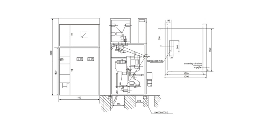
9Dimensions(Width * depth * height)mm1100*1200*2650(1250A and Below)
10IP CodeIP2X

Drawing of High and Low Voltage Switchgear XGN2-12

switchgear structure
Please enable JavaScript in your browser to complete this form.

Get in Touch

Transformer Substation Product

Transformer Substation

Transformer Substation

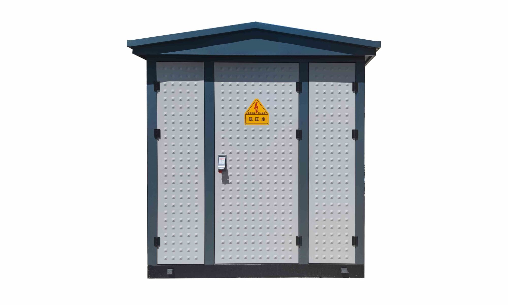
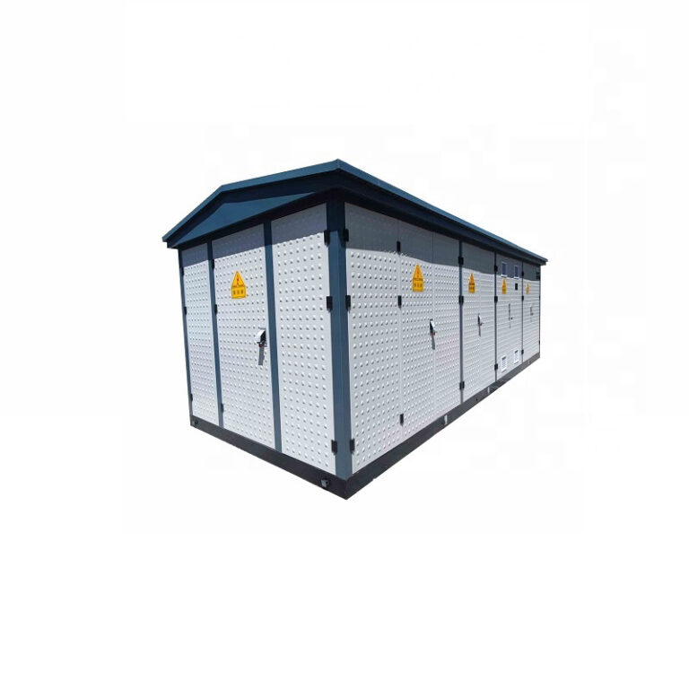
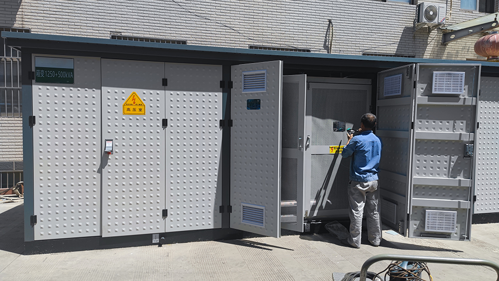
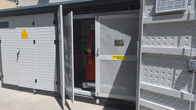
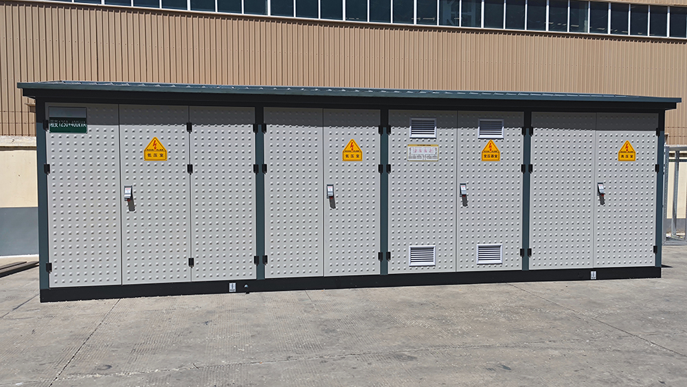
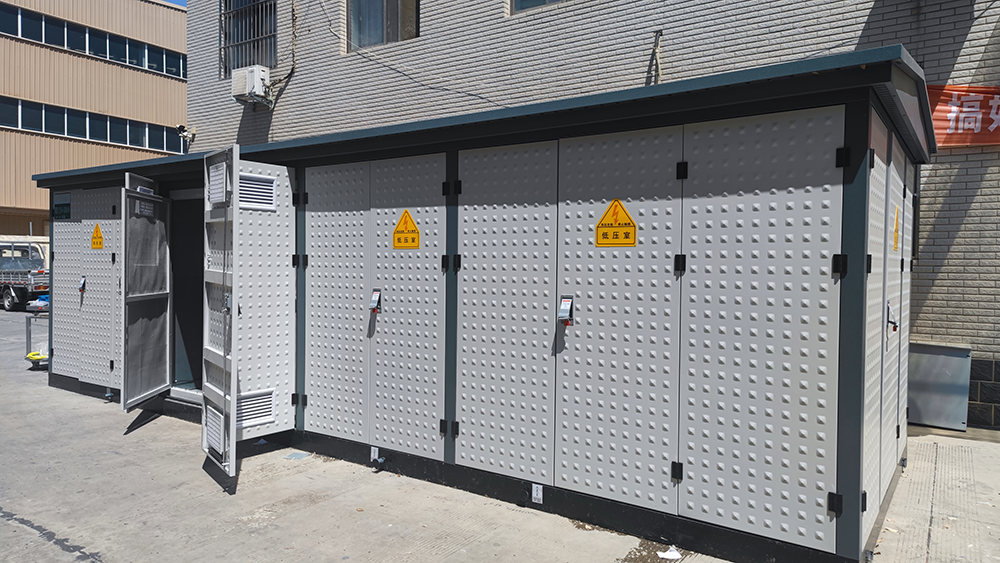
BYT Transformer Substation has attracted extensive attention because of its advantages of flexible combination, convenient transportation, convenient relocation, convenient installation, short construction period, low operating cost, small footprint, no pollution, and maintenance-free. The box-type transformer substation is mainly composed of a multi-loop high-voltage switchgear system, a substation integrated automation system, capacitance compensation and DC power supply and other electrical units, which are installed in a moisture-proof, rust-proof, dust-proof, rodent-proof, fireproof, anti-theft, heat-insulated, fully enclosed, movable steel structure box, mechatronics, fully enclosed operation.

Introduction of Transformer Substation

  1. The box body adopts domestic leading technology, and the shell is generally made of galvanized steel plate. The frame adopts standard container materials and manufacturing techniques. It has good anti-corrosion performance and guarantees no corrosion for 20 years. The inner sealing plate adopts aluminum alloy buckle plate, and the interlayer adopts fireproof and thermal insulation materials, air-conditioning and dehumidification devices are installed in the cabinet, and the operation of the equipment is not affected by the natural climate environment and external pollution, and can ensure normal operation in the harsh environment of -40℃~+40℃.
  2. The product has a high degree of automation, perfect high and low voltage protection, safe and reliable operation, and simple maintenance.
  3. It occupies a small area, saves investment, has a short production cycle, is convenient to move, and has flexible and diverse wiring schemes.
  4. Factory prefabrication, as long as the designer according to the actual requirements of the substation, make a main wiring diagram and the design of the equipment outside the box, you can choose the specifications and models of the box transformer provided by the manufacturer.
  5. The transformer substation has a beautiful appearance and a variety of types, including general-purpose, villa-type, compact and other styles. By selecting the color of the box-type substation shell, it is easy to coordinate with the surrounding environment, which is especially suitable for urban construction.

Transformer substations are vital for the stability and reliability of the electrical grid. They ensure that electricity can be transmitted over long distances with minimal losses and delivered safely to homes and businesses. Proper design, operation, and maintenance of these substations are essential for the overall efficiency of the power system.

Technical Specification of Transformer Substation

No.ItemUnitValue
1Rated VoltagePrimaryKV40.5
Secondary12; 0.69
Subsidiary CircuitV110;220;380
2Rated CurrentHigh Voltage CircuitA400~1250
Low Voltage Circuit630~3150
3Rated FrequencyHz50
4Rated PowerKvA1250; 1600; 2000~20000
5Rated
Insulation
Level
High Voltage SidePower FrequencyKV95
Impact185
Low Voltage SidePower Frequency42
Impact74
6Rated Short Time Withstand CurrentHigh Voltage SideKA20; 25; 31.5
Low Voltage Side25; 31.5; 40
7Rated Peak Withstand CurrentHigh Voltage Side50; 63; 80
Low Voltage Side63; 80; 100
8Insulation Level of TransformerPower FrequencyKV65
Impact185
9Insulation Level of Subsidiary Circuit2
Please enable JavaScript in your browser to complete this form.

Get in Touch

333KVA Single Phase Pole Mounted Transformer

single phase pole mounted transformer

Single Phase Pole Mounted Transformer

333KVA Single Phase Pole Mounted Transformer

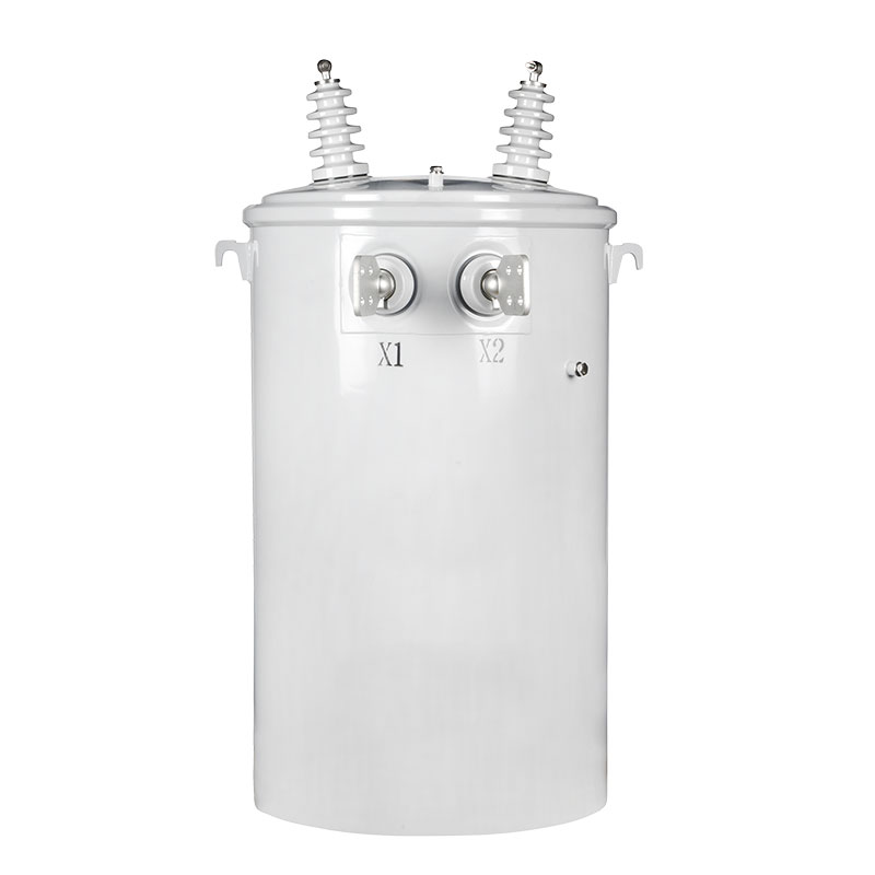
The 333KVA Single Phase Pole Mounted Transformer is a versatile and reliable electrical device used for power distribution in single-phase systems. With a power rating of 333KVA, this transformer is capable of handling significant electrical loads, making it suitable for a wide range of applications. It is built with high-quality materials and components to ensure long-term performance and reliability. The transformer is also equipped with advanced insulation and protection features to safeguard against electrical faults and ensure safe operation.

single phase transformer

Introduction of 333KVA Single Phase Pole Mounted Transformer

BYT 333KVA Single Phase Pole Mounted Transformer is built to last, with durable construction and advanced technology that ensures reliable performance. Whether you are looking to upgrade your current transformer or install a new one, this transformer is a great choice for your power distribution requirements.


The Application of 333KVA Single Phase Pole Mounted Transformer:

  • Residential Areas: This transformer is often installed in residential neighborhoods to distribute power to homes, apartments, and other residential buildings. It helps step down the high-voltage electricity from the distribution lines to a lower voltage suitable for household appliances and lighting.
  • Commercial Buildings: The transformer is also used in commercial settings such as offices, retail stores, and small businesses to provide reliable power supply for lighting, HVAC systems, computers, and other equipment.
  • Industrial Facilities: In industrial applications, the 333KVA transformer is used to power machinery, equipment, and production processes in factories, manufacturing plants, and industrial complexes. It helps ensure a stable and efficient power supply for critical operations.
  • Rural Areas: The pole-mounted transformer is commonly installed in rural areas where overhead power distribution lines are used. It helps bring electricity to remote locations, farms, and agricultural facilities, improving the quality of life and enabling economic development.

Technical Specification of Single Phase Pole Mounted Transformer

Technical Specs
Rating333 KVA
TypePole-Mounted Distribution Transformer
No. of Phases1
Frequency60 Hz
Primary Voltage25/37.5 KV
Secondary Voltage120/240/480 V
Tapping Range±2 x 2.5%
Winding MaterialCopper / Aluminum
Core MaterialGrain Oriented Silicon Steel Sheet
Impedance1.5 – 6.0 %
Efficiency99.43%
Cooling TypeONAN
Average Winding Rise55 °C, 55/65 °C, 65 °C
Fluid TypeNon-PCB Mineral Oil / FR3 Biodegradable
Tap ChangerOff-Load Tap Changer
IEEE StandardsC57.12.00, C57.12.20, C57.12.31, C57.12.35, C57.12.90, C57. 91 and C57.154
NEMA StandardNEMA TR 1
Tank CoatingIEEE Std C57.12.31-2010

Drawing of Single Phase Pole Mounted Transformer

single phase pole mounted transformer structure
Please enable JavaScript in your browser to complete this form.

Get in Touch

250KVA Single Phase Pole Mounted Transformer

single phase pole mounted transformer

Single Phase Pole Mounted Transformer

250KVA Single Phase Pole Mounted Transformer

BYT 250KVA Single Phase Pole Mounted Transformer is a robust and reliable electrical device designed to efficiently distribute power in single-phase electrical systems. With a power rating of 250 kilovolt-amperes, this transformer is capable of handling a significant amount of electrical load, making it ideal for various applications in residential, commercial, and industrial settings. Mounted on a pole for easy installation and maintenance, this transformer plays a crucial role in stepping down high-voltage power from the primary side to a lower voltage suitable for local distribution. Its compact design and sturdy construction ensure reliable performance and long-term durability, even in challenging environmental conditions.
Equipped with advanced insulation and protection features, the 250KVA Single Phase Pole Mounted Transformer offers safe and efficient power distribution, contributing to the smooth operation of electrical systems and ensuring a reliable supply of electricity to end-users. Whether used in urban or rural areas, this transformer is a vital component of modern electrical infrastructure, providing essential power distribution capabilities to support various electrical loads.

single phase transformer

Introduction of 250KVA Single Phase Pole Mounted Transformer

The Features of the 250KVA Single Phase Pole Mounted Transformer:

  1. High Efficiency: The transformer is designed to minimize energy losses during power conversion, ensuring efficient operation and reduced electricity consumption.
  2. Robust Construction: Built with high-quality materials and components, the transformer is durable and able to withstand harsh environmental conditions, such as extreme temperatures, humidity, and vibrations.
  3. Advanced Insulation: The transformer is equipped with advanced insulation materials and techniques to protect against electrical faults and ensure safe operation.
  4. Overload Protection: The transformer is designed with overload protection mechanisms to prevent damage from excessive electrical loads and ensure long-term reliability.
  5. Compact Design: The transformer’s compact size and pole-mounted installation make it suitable for applications where space is limited or where underground installation is not feasible.
  6. Easy Maintenance: The transformer is designed for easy access and maintenance, allowing for quick inspections, repairs, and replacements as needed.
  7. Compliance with Standards: The transformer meets relevant industry standards and regulations for electrical safety and performance, ensuring reliable and compliant operation.

Technical Specification of Single Phase Pole Mounted Transformer

Technical Specs
Rating250 KVA
TypePole-Mounted Distribution Transformer
No. of Phases1
Frequency60 Hz
Primary Voltage25/37.5 KV
Secondary Voltage120/240/480 V
Tapping Range±2 x 2.5%
Winding MaterialCopper / Aluminum
Core MaterialGrain Oriented Silicon Steel Sheet
Impedance1.5 – 6.0 %
Efficiency99.39%
Cooling TypeONAN
Average Winding Rise55 °C, 55/65 °C, 65 °C
Fluid TypeNon-PCB Mineral Oil / FR3 Biodegradable
Tap ChangerOff-Load Tap Changer
IEEE StandardsC57.12.00, C57.12.20, C57.12.31, C57.12.35, C57.12.90, C57. 91 and C57.154
NEMA StandardNEMA TR 1
Tank CoatingIEEE Std C57.12.31-2010

Drawing of Single Phase Pole Mounted Transformer

single phase pole mounted transformer structure
Please enable JavaScript in your browser to complete this form.

Get in Touch

167KVA Single Phase Pole Mounted Transformer

single phase pole mounted transformer

Single Phase Pole Mounted Transformer

167KVA Single Phase Pole Mounted Transformer

BYT 167KVA single phase pole mounted transformer is a high-capacity and robust electrical distribution solution. With its efficient operation and durable construction, this transformer is ideal for industrial and commercial applications. The easy installation on utility poles saves time and labor costs, while the advanced safety features ensure reliable performance. Designed for high efficiency in voltage conversion, the BYT 167KVA transformer minimizes energy losses and enhances overall system performance. Trust the BYT transformer for your heavy-duty electrical distribution needs.

single phase transformer

Introduction of Single Phase Pole Mounted Transformer

The working principle of the 167KVA single-phase pole-mounted transformer:

  • Primary Coil: The primary coil of the transformer is connected to the high-voltage power source. When an alternating current (AC) flows through the primary coil, it creates a changing magnetic field around the coil.
  • Secondary Coil: The secondary coil of the transformer is connected to the load or electrical system that requires the transformed voltage. The changing magnetic field induced by the primary coil causes a voltage to be induced in the secondary coil through electromagnetic induction.
  • Voltage Transformation: The ratio of the number of turns in the primary coil to the number of turns in the secondary coil determines the voltage transformation ratio of the transformer. In the case of a 167KVA transformer, the primary voltage is stepped down to a lower voltage suitable for the connected load.
  • Power Transfer: The transformed voltage in the secondary coil is then supplied to the load, providing the necessary electrical power for operation.

Technical Specification of Single Phase Pole Mounted Transformer

Technical Specs
Rating167 KVA
TypePole-Mounted Distribution Transformer
No. of Phases1
Frequency60 Hz
Primary Voltage25/37.5 KV
Secondary Voltage120/240/480 V
Tapping Range±2 x 2.5%
Winding MaterialCopper / Aluminum
Core MaterialGrain Oriented Silicon Steel Sheet
Impedance1.5 – 4.5 %
Efficiency99.33%
Cooling TypeONAN
Average Winding Rise55 °C, 55/65 °C, 65 °C
Fluid TypeNon-PCB Mineral Oil / FR3 Biodegradable
Tap ChangerOff-Load Tap Changer
IEEE StandardsC57.12.00, C57.12.20, C57.12.31, C57.12.35, C57.12.90, C57. 91 and C57.154
NEMA StandardNEMA TR 1
Tank CoatingIEEE Std C57.12.31-2010

Drawing of Single Phase Pole Mounted Transformer

single phase pole mounted transformer structure
Please enable JavaScript in your browser to complete this form.

Get in Touch