High and Low Voltage Switchgear
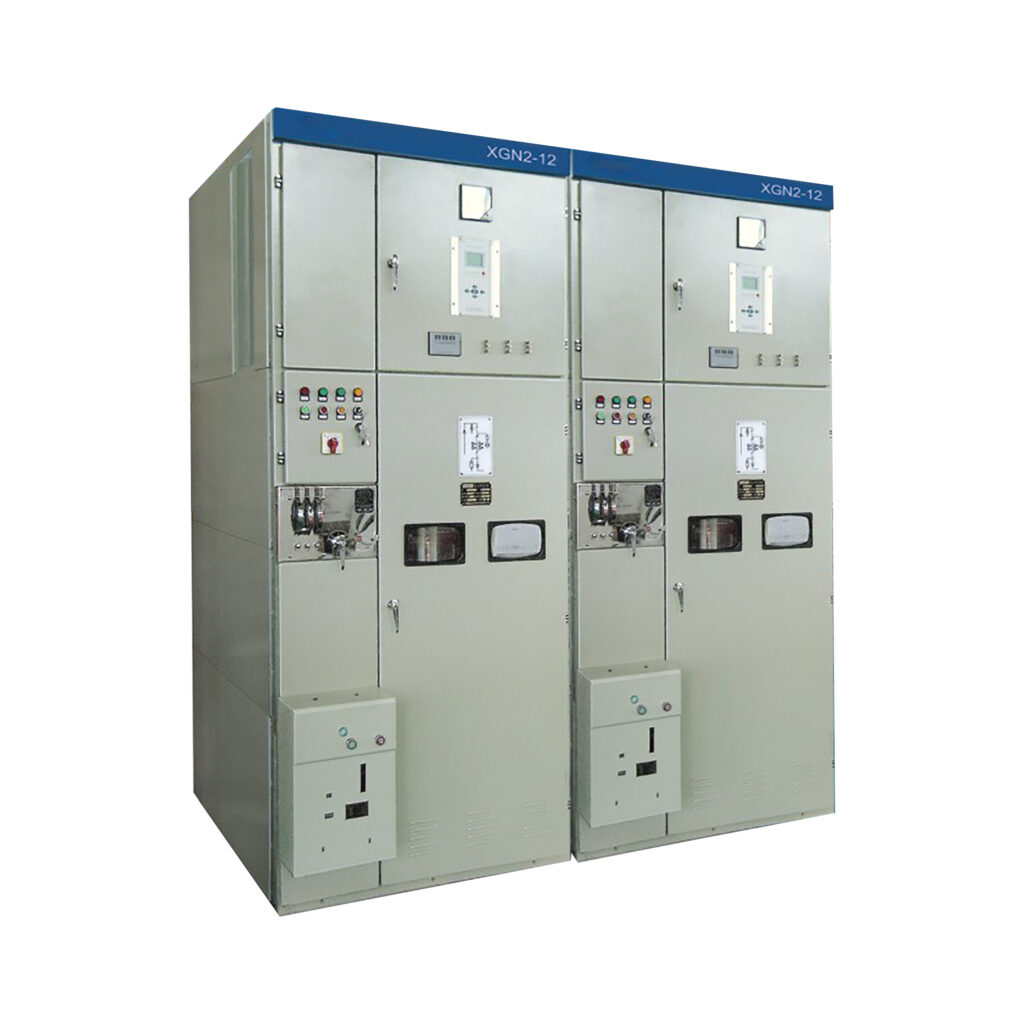
High and Low Voltage Switchgear XGN2-12
- Ambient temperature: High temperature 45°C, low temperature -35°C
- Daily temperature difference: No more than 25°C
- Earthquake tolerance: Earthquake intensity does not exceed 8°C
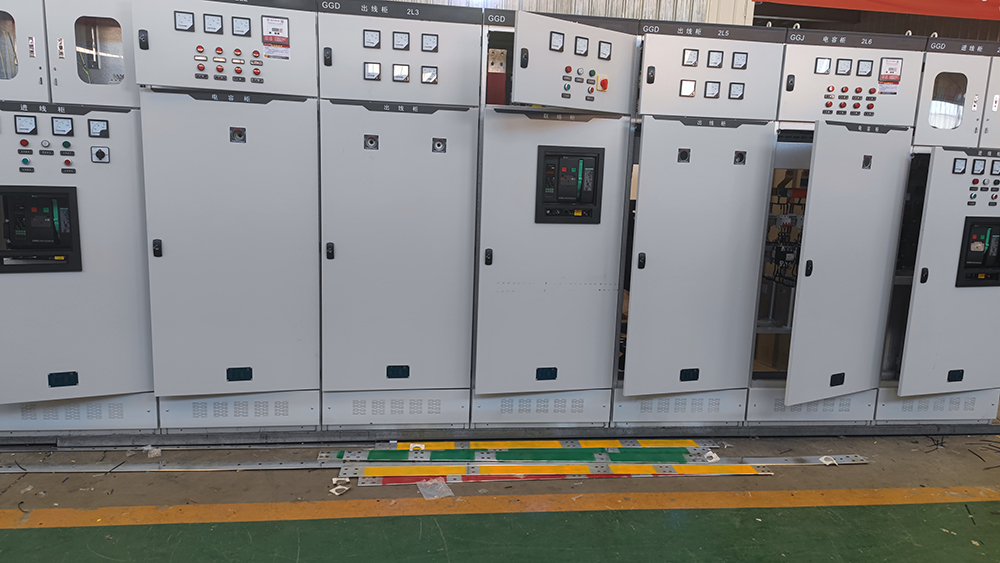
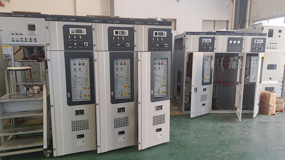
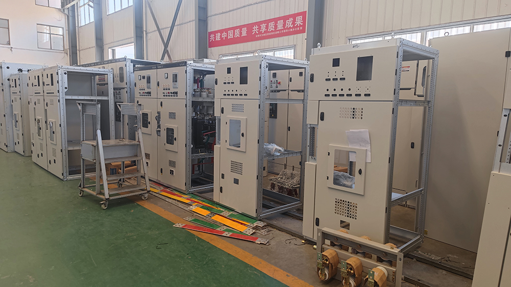
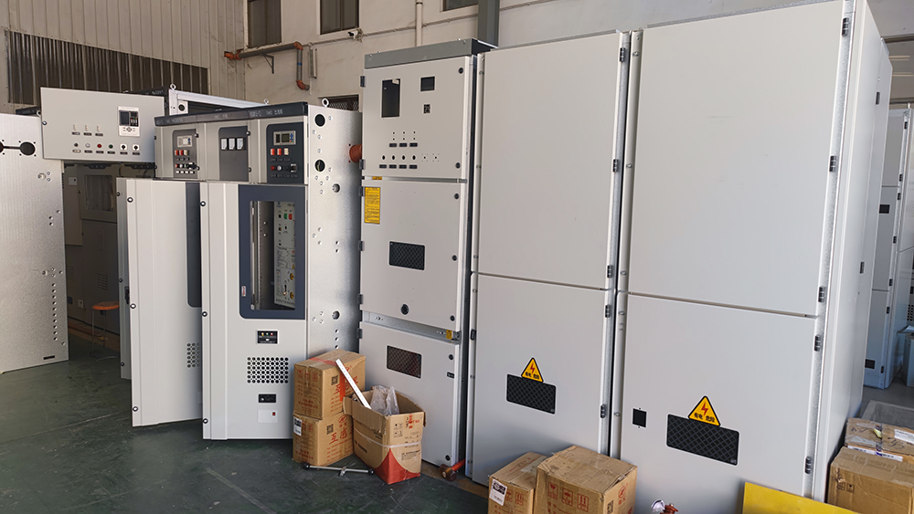
The XGN2-12 switchgear features a metal-enclosed box structure. The cabinet frame was originally designed to be welded from angle steel, but after development by our company, it can also be constructed using bent steel plates. This not only greatly enhances the aesthetic appearance but also facilitates production organization and shortens the production cycle. The cabinet is divided into compartments for the circuit breaker, busbar, cable, and relay, with steel plates separating each compartment.
Introduction of High and Low Voltage Switchgear XGN2-12
The XGN2-12 box-type fixed metal-enclosed switchgear is used in three-phase AC systems with a voltage of 12kV and below, operating at a frequency of 50Hz, for the purpose of receiving and distributing electrical energy. It is particularly suitable for applications that require frequent operation. The busbar system consists of a single busbar (which can also be configured as a single busbar with a bypass or a double busbar structure).
Some structural features of High and Low Voltage Switchgear XGN2-12:
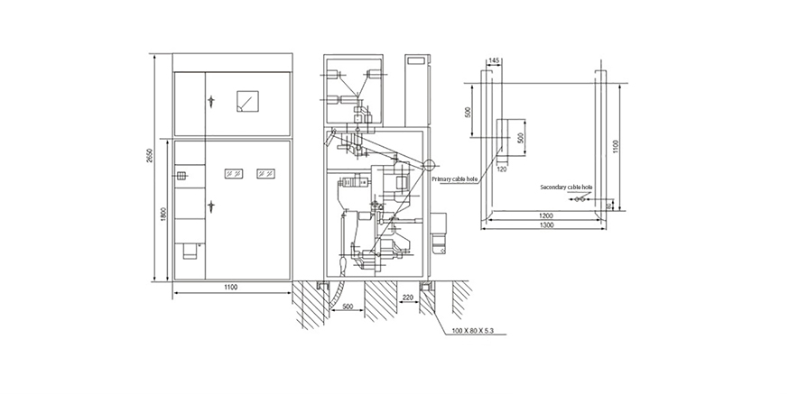
- The circuit breaker chamber is located at the lower front part of the cabinet. The rotation of the circuit breaker is connected to the operating mechanism via a pull rod. The upper terminal of the circuit breaker is connected to the upper isolating switch, while the lower terminal is connected to the current transformer. The current transformer is connected to the busbar of the lower isolating switch. Additionally, the circuit breaker chamber is equipped with a pressure relief channel, allowing gas to be released through the exhaust channel in the event of an internal arc.
- The busbar chamber is located at the upper rear part of the cabinet. To reduce the height of the cabinet, the busbars are arranged in a U-shape and supported by porcelain insulators with a bending strength of 7350N. The busbars are connected to the busbar of the upper isolating switch, and isolation is possible between adjacent busbar chambers.
- The cable chamber is located at the lower rear part of the cabinet. Insulators in the cable chamber may be equipped with voltage monitoring devices, and the cables are secured to the brackets. When the main wiring is configured as a connection scheme, this chamber serves as a connection sub-chamber. The relay chamber is situated at the upper front part of the cabinet, where mounting plates can accommodate various relays and other devices. There are terminal block supports inside, and the door can be fitted with indicating instruments, signal elements, and other secondary components. Additionally, a secondary small busbar can be arranged at the top.
Technical Specification of High and Low Voltage Switchgear XGN2-12
| No. | Item | Unit | Technical parameters | |||||||
|---|---|---|---|---|---|---|---|---|---|---|
| 1 | Rated voltage | KV | 12 | |||||||
| 2 | Maximum Operating Voltage | KV | 12 | |||||||
| 3 | Rated Current | A | 630 | 1000 | 1000 | 1250 | 2000 | 2500 | 3150 | |
| 4 | Rated Short Circuit Interrupting Current | KA | 20 | 31.5 | 40 | |||||
| 5 | Rated Short-time Withstand Current(4S) | KA | 20 | 31.5 | 40 | |||||
| 6 | Rated Peak Withstand Current | KA | 50 | 80 | 100 | |||||
| 7 | Rated Short Circuit Breaking Current(Peak) | KA | 50 | 80 | 100 | |||||
| 8 | Operating Mode | Electromagnetic/Spring Energy Storage/Electromotor/Manual | ||||||||
| 9 | Dimensions(Width * depth * height) | mm | 1100*1200*2650(1250A and Below) | |||||||
| 10 | IP Code | IP2X | ||||||||
Drawing of High and Low Voltage Switchgear XGN2-12
Get in Touch
- Sales Manager: Eric
- Phone: +86-15515007426
- Whatsapp: +86-15515007426
- Factory Address: Beiyoute Industrial Park, Xujia Gou Town, Yindu District, Anyang City

